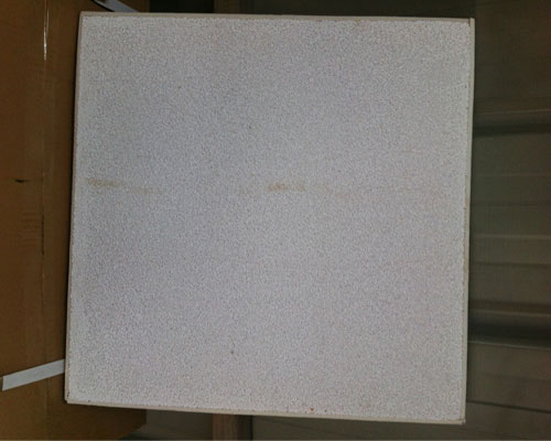
The size of each Ceramic Foam Filter Type is 5″×5″×1″ thick, and it is designed to have an air permeability of 1750×10-7 cm2, a porosity of 0.90, and a pore size of 30 holes per linear inch. 25 in each row and then in each Holes of the same size are drilled on each filter. It should be noted that in addition to introducing the holes into the final filter product by drilling or similar methods, the holes can also be introduced into the soft foam material before processing.
Preferably, the holes have the same size and are evenly distributed on the entire surface of the filter plate, so that the flux gas is evenly distributed on the filter plate. 0.10″ to 0.45″ in increments of 0.05″. The filter was then incorporated into a pilot-scale device to study the countercurrent gas-liquid flow characteristics of the filtration and degassing process. The liquid was measured at 924 in.3 per minute. The rate of 1386 in.3 per minute and 1848 in.3 per minute is introduced into the filtration and degassing chamber.
By providing a preferential flow path for combustion-supporting gas through the ceramic foam filter plate, the pressure difference across the filter plate is reduced, resulting in a corresponding reduction in the pressure head difference, which allows the use of a correspondingly smaller unit, while improving the degassing efficiency . It has been found that a pore size of up to 0.45 inches can be effectively used without substantially reducing the filtering function of the filter plate.
The filter profile is arranged substantially horizontally. The equipment is provided with an inlet launder leading to the chamber, and filtering and degassing operations are performed in the chamber. The chamber is shown as roughly bowl-shaped, and its bottom is recessed below the height of the inlet launder, so that the molten metal traveling on it will flow downward through the Ceramic foam filter type media.

