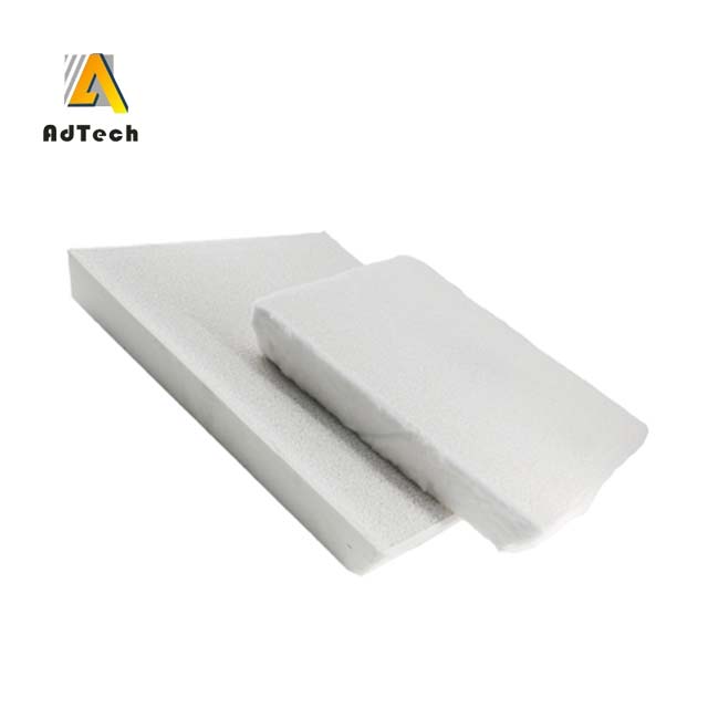
A Porous ceramic filter is a porous ceramic product with a porosity of 70% to 90%, a three-dimensional network skeleton, and a structure of interpenetrating pores.
It is widely used in the filtration of molten metal liquid of non-ferrous alloys, cast iron, and cast steel. The production process is as follows: with foam plastic as the skeleton,
It is coated with ceramic slurry and fired at a high temperature.
Since the porous ceramic filters have a three-dimensional network structure, the filtering mechanism is as follows: by selecting the porous ceramic filters with appropriate pore size, the molten metal is stored in the molten metal.
In the presence of a large number of oxide inclusions, slag, and other large impurities, mechanical methods are used to screen and filter; as the number of captured inclusions increases,
A “filter cake” composed of large inclusions is formed on the surface of the filter inlet to enhance the filtering effect; the porous ceramic filter has a large surface inside
It is beneficial to adsorb a large number of fine impurity points. At the same time, after the liquid metal passes through the porous ceramic filter, the liquid metal changes from turbulent flow to laminar flow, changing the flow.
The dynamic state makes the filling more stable. Therefore, it can effectively improve the defects of slag inclusion, reduce the content of gas and harmful elements in the molten metal, and improve the composition
Weave structure, improve mechanical properties, improve the overall yield and surface quality of castings
The size, quantity, and composition of the filtered slag inclusions were analyzed by optical microscope and scanning electron microscope. have to
The distribution law of the slag inclusions filtered by the filter plate verifies the adsorption effect of the porous ceramic filters.

1 Sample processing
Take the poured 432×432×50mm 50ppi porous ceramic filter and cut the porous ceramic filter into pieces as shown in Figure 1. cut
After that, the test block is cut along the horizontal direction. The cutting method is shown in Figure 2.
The samples with the label of 3 vertical sections were selected for analysis, and after horizontal cutting, they were numbered from top to bottom, and the numbers were S31, S32, and S33, respectively.
The cut filters are treated, polished, ultrasonically cleaned (cleaned in absolute ethanol), and then irradiated with a Leica DM2700 M light
The processed samples were photographed and analyzed by a metallographic microscope, and the defect distribution of the upper, middle and lower sections was analyzed. At the same time using KEYENCE VHX-5000
Defects are observed with a super-depth-of-field microscope. Electron microscopy and energy analysis of each sample were performed using a German Zeiss EVO18 field emission scanning electron microscope.
Spectral analysis observation.
